Monacor SA-800 Part I
This post is the first post in a cycle concerning analysis of electronic circuit of Monacor Solid State Stereo SA-800 Amplifier. It is an audio amplifier produced in the 70s [1]. Official amplifier documentation is not available at the manufacturer website. The main source of information about the amplifier was www.radiomuseum.org, which has photos of amplifier documentation (including electronic circuit). It is available at [1].
As mentioned before the cycle concerns the electronic circuit of the amplifier. This post describes inputs and outputs of the device and gives a high-level overview on the main circuit parts. In subsequent articles I will discuss these parts in detail. I plan to redraw the circuit parts from the document downloaded from www.radiomuseum.org into KiCad and attach them to posts. However some electronic components do not have SPICE models (probably because most of them are no longer produced). For such components I will use replacement components which have available SPICE models. Another problem is that values of some electronic elements in the image with the circuit are blurred/vague. Therefore I may unintentionally assume bad element values. Finally, some parts of documentation were unclear to me. For those parts I will make assumptions of how I interpret a given part (I will mark all places with assumptions).
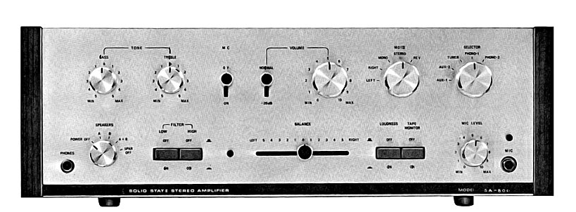
Below photo shows monacor SA 800 (source):
1. Inputs, outputs, control elements
Documentation of device inputs and outputs is available at [1] in “SCHEMATICS” tab. It is written in German. Below I provide a translated and simplified version of inputs and outputs description. I skipped information that is not necessary to understand the operation of the amplifier circuit.
Device inputs:
- PHONO 1 - magnetic gramophone input. Possible input impedance of amplifier for PHONO 1 can take values 30kΩ or 50kΩ and is regulated witch the PHONO 1 IMPEDANCE switch.
- PHONO 2 - magnetic gramophone input. Input impedance of amplifier for PHONO 2 is 50kΩ.
- AUX 1 - high level inputs like gramophones with crystal and ceramics transducer (see [2] for details).
- AUX 2 - high level inputs like gramophones with crystal and ceramics transducer.
- Tuner - FM- and AM/FM-Stereo receiver input. Receivers can also be connected to AUX inputs.
- MAIN IN - discussed along with PRE OUT output.
- SWITCHED power supply connector - supplies the circuit with electricity, when the device is switched on. It can deliver up to 150W.
- UNSWITCHED power supply connector - supplies the circuit with electricity regardless of whether the device is turned on or off. Can deliver up to 300W.
- MIC connector - input for dynamic microphone.
Device outputs:
- Tape - output for magnetophon that can record sound coming from the selected input. Recorded sound is not altered by amplifier regulators (like treble). This connector can probably also act as an input (see TAPE MONITOR).
- Tape out - additional output for magnetophon that records sound from the selected input after applying all available regulators. Sound coming from microphone can also be recorded through this output
- PRE OUT - this output enables plugin of an additional device (e.g. echo unit), between boards NPP-OIA and NPA-OI (see next section for boards description). Input of such device is connected to PRE OUT (output of NPP-OIA) and output is connected to MAIN IN (input of NPA-OI).
- MONO OUT - the output conveys signal from combined two stereo channels into a single signal. Signal coming from MONO OUT connector is not amplified as much as signals passed to main speakers output. An additional amplifier is needed between the MONO OUT and loudspeakers.
- PHONES - headphones output.
Control elements:
- PRE OUT/MAIN IN control switch - the switch can be in positions NORMAL and SEPARATE. In NORMAL position boards NPA-OI and NPP-OIA are connected. In SEPARATE positions these boards are disconnected and connection between them needs to be formed using PRE OUT and MAIN IN.
- input selector - allows to select one of the inputs: PHONE 1, PHONE 2, AUX1, AUX2, TUNER.
- operation mode switch - specifies mode of operation. Following modes are available: LEFT (RIGHT) - only signal from left(right) channel is provided to the speakers, MONO - combined sound from both channels is provided to the speakers, STEREO - stereo operation, REV - stereo operation, but left and right channel are swapped compared to STEREO.
- volume knob - regulates volume level for both channels.
- volume switch - has values NORMAL and -20dB. In position -20dB the sound is quieter by 20dB than in NORMAL position.
- MIC switch - turns on microphone input.
- TREBLE knob - amplifies or suppresses high frequency tones.
- BASS knob - amplifies or suppresses low frequency tones.
- SPEAKERS selector - turns on power supply and selects speakers. Following options are available: POWER OFF - the device is turned off, A (B) - signal is delivered only to speakers with a symbol A (B), A+B - signal is delivered to both speakers, SPKR OFF - signal is delivered only to headphones output.
- LOW filter - when turned on, the filter suppresses low frequencies.
- HIGH filter - when turned on, the filter suppresses high frequencies.
- balance - regulates power ratio of signal provided to left and right channels.
- LOUDNESS button - pressing the button enables switching between linear sound volume regulation and equal-loudness sound volume regulation.
- TAPE MONITOR - when the button is pressed Tape starts acting as an input and only recording from Tape will be heard (no input selected from input selector will be heard). I am not entirely sure whether I correctly understood this description. If, after detailed circuit analysis, I find out that my interpretation was incorrect I will update the description.
- MIC LEVEL - controls sound level for the microphone.
- PHONO 1 IMPEDANCE switch - allows to change impedance of PHONO 1 input between 30kΩ and 50kΩ.
Other elements:
- fuses - there are a few fuses to protect the circuit. Their detailed description is skipped.
- lights - signalize turning on some switches. Their description is skipped.
2. Electronic circuit
Image of the circuit is provided below. I downloaded it from [3].
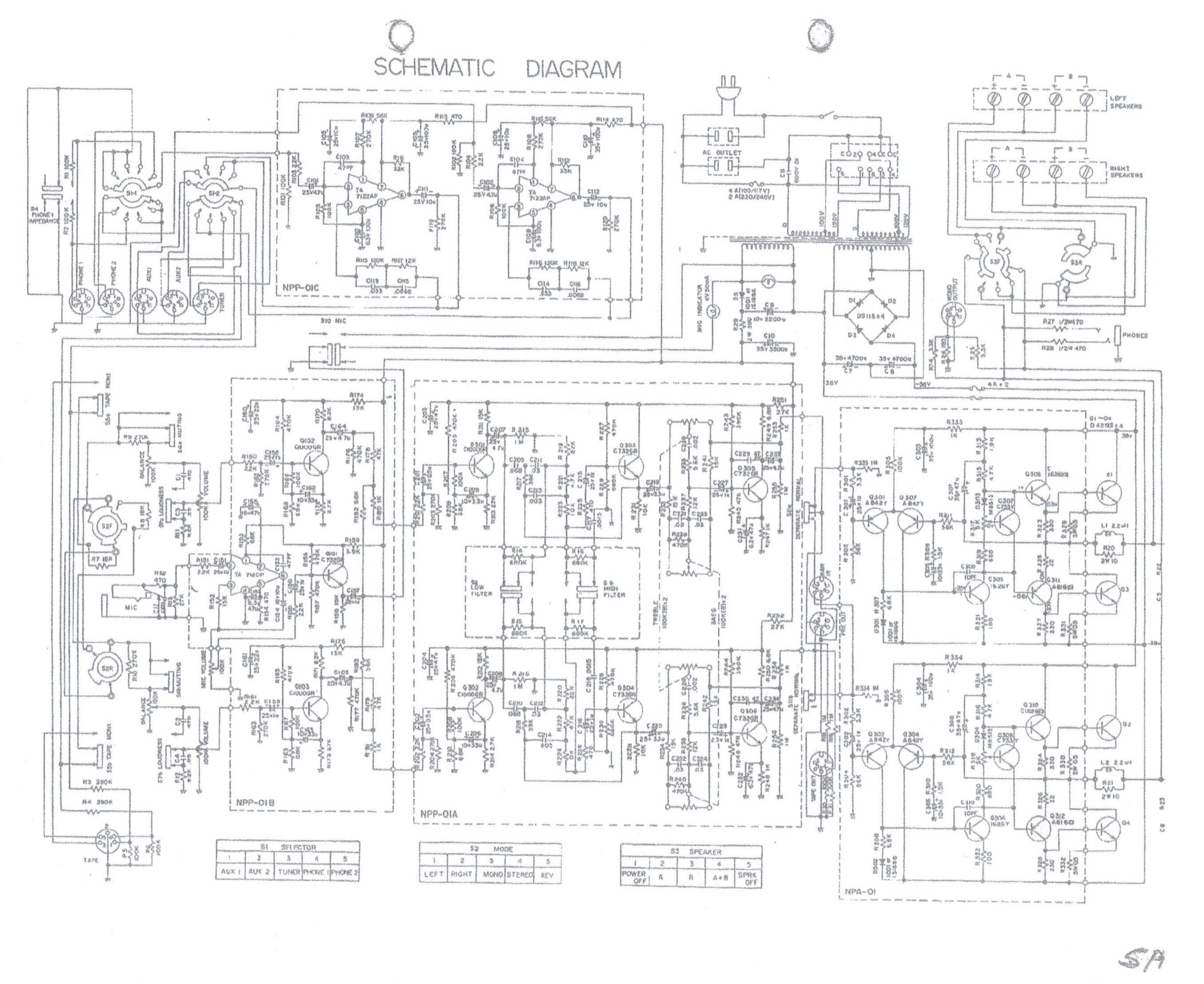
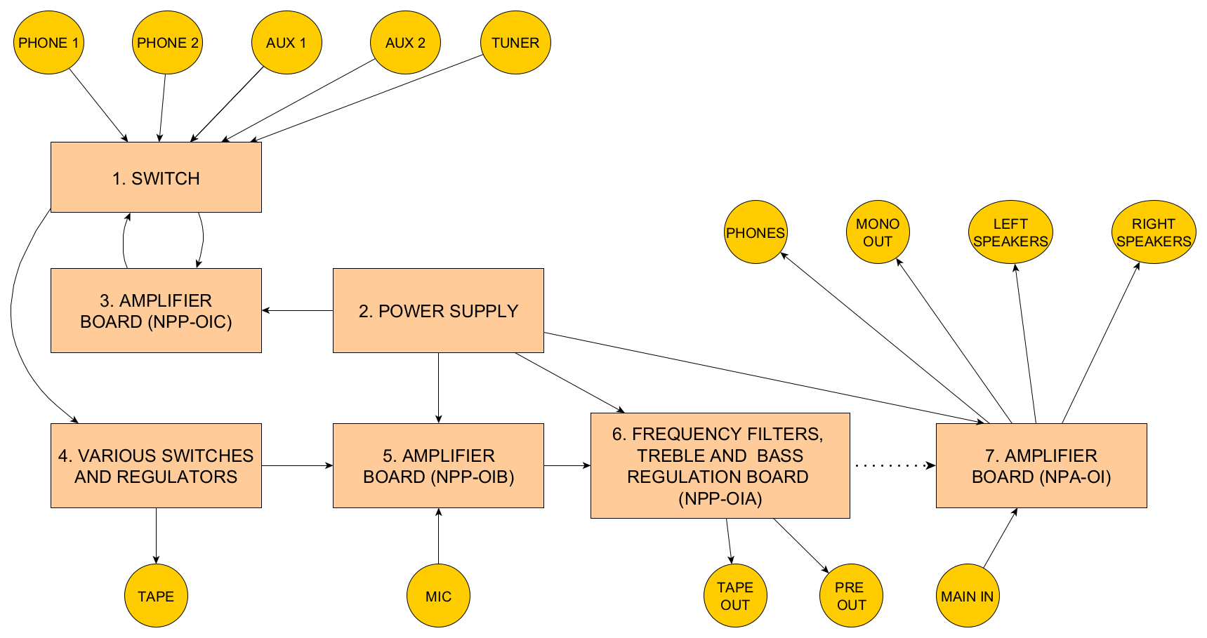
There are four boards on the diagram. Borders of each board are marked with dashed lines. Their identifiers can be found at the left bottom of board areas. Part of electronic elements, inputs and outputs are not located on any board of this circuit. I highlighted the following main functional components of the amplifier circuit (it is my subjective division based o circuit analysis - there may exist better ways to split the circuit into parts):
- Switch - selects signal from one of the amplifier inputs and passes it to the NPP-OIC board. It also takes output from NPP-OIC board and conveys it to further parts of the amplifier. Following inputs are connected to the switch: PHONE 1, PHONE 2, AUX1, AUX2, TUNER.
- Power supply - connects to outlet with AC, converts it into DC and supplies the whole circuit with symmetrical voltage -38V/+38V.
- Voltage amplifier board no 1 - located on board NPP-OIC. It amplifies voltage level of raw input signals from the switch and passes it back to the same switch.
- Various switches and regulators - this circuit part takes amplified input signals from the switch, applies MUTING, BALANCE and VOLUME level regulations and passes it to NPP-OIB. Unmodified by regulators input signal is passed to Tape output for recording (apart from case when TAPE MONITOR is pressed - in such case signal from Tape is processed instead of signal from the switch).
- Voltage amplifier board no 2 - located on board NPP-OIB. It amplifies voltage level of signal from “Various switches and regulators” part and takes MIC input. It transmits signal to NPP-OIA board.
- Frequency filters, treble and bass regulation board - located on board NPP-OIA. It takes signal from NPP-OIB, applies low and high filters and adjusts bass and treble frequencies. Every of these functionalities can be regulated or turned on/off independently. The signal is then passed to TAPE OUT and either to board NPA-OI or PRE OUT.
- Power amplifier board - located on board NPA-OI. It amplifies power of the signal coming from NPP-OIA or MAIN IN. Amplified signal can be transmitted either to loudspeaker, MONO OUTPUT or phones.
Below diagram shows the forementioned components and connections between them: