DIY Audio Amplifier Project Part II
This post is a continuation of the two-part series of posts describing the audio amplifier I built. The first article can be accessed at this link. This post presents the physical construction of the device. It discusses defects of the amplifier of which I became aware after constructing the physical device. Process of starting the device, adding corrections to address the found issues and performance of the amplifier is also provided here.
Prerequisites: Requirements, design and SPICE simulations of the amplifier are discussed in the previous article, so it may be helpful to read it first. The article does not explain basic concepts of electronics, electronic elements and building blocks of electronic circuits that are widely known and their descriptions can be easily found on the Internet.
Acknowledgements: Thank you to Joachim for helping me with this project.
1. Physical construction of the boards
Electronic design is discussed in detail in the previous post about the amplifier, so this section just describes physical aspects of creating boards for circuits. Electronic circuitry is split into main amplifier board containing the amplifier and powering board for providing power supply to the amplifier board.
Decision to have two boards instead of one has the following advantages:
- complexity of electronic circuitry of separate boards for powering and amplifying modules is smaller than complexity of one board having both modules. It is easier to analyze and debug.
- amplifying module can be tested separately from powering module by using ready power supply (e.g. KORAD power supply) to temporarily provide power supply.
- it is possible to construct amplifying and powering modules on different types of board - board for amplifier module was PCB and board for powering module was a universal THT board.
1.1 Main amplifier board
I made a PCB for the main amplifier part. To design the PCB I used PCB Editor from KiCad. Maximum current that is supposed to flow through the first two amplifier stages is not expected to exceed a few mA. Therefore I could use SMD mounting for their elements. SMD allows to limit surface needed for elements compared to THT and avoids drilling the board as in case of THT. The output stage is intended to pass a relatively big current (up to around 1A). SMD elements could get burned while conveying such current, so THT mounting needed to be used. SMD elements were located on one side of PCB board, THT elements on the other. More details about the PCB can be found in KiCad project. Radiators were attached to output stage transistors for heat dissipation (radiators are not present in KiCad model). Resistors R4 and R18 were cement power resistors able to conduct current of the order of magnitude 1A.
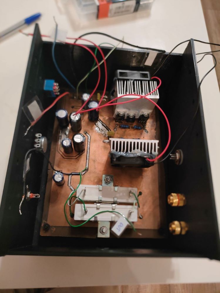
Photos of the PCB board I built are provided below. These photos were taken before fixing issues I detected after starting-up the amplifier.
Front side of the board (according to KiCad PCB project). It contains SMD elements from input stage and voltage amplifier stage:
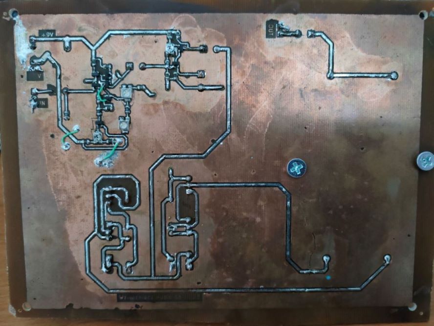
Back side of the board (according to KiCad PCB project). It contains THT elements from output stage:
1.2 Powering board
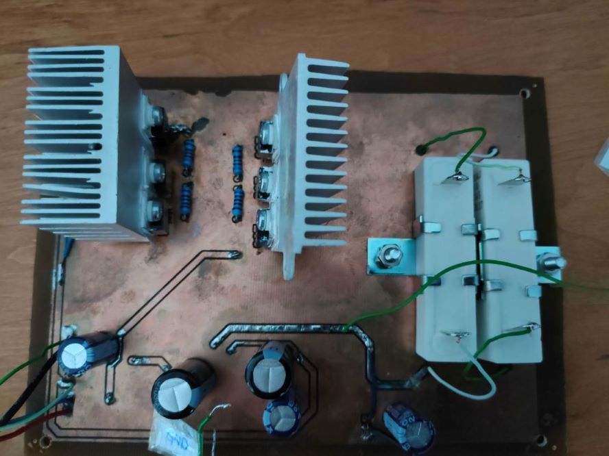
I made powering board using universal board and THT elements. The work to assemble the circuit was really straightforward. In addition to what was mentioned in the previous post I added radiators for heat dissipation on LM337 elements to avoid overheating. The input to the powering board was a transformer 250/12V. After assembling the th board and transformer, multimeter reported negative and positive output voltages to be around -9.41V and 9.08V respectively. This was not exactly equal to desired -9V and 9V, but I decided to accept that.
This is the photo of the ready powering board with transformer:
2. Starting up the amplifier
After constructing the main amplifier board I tested its operation (separately from powering board).
2.1 Initial starting-up attempts
I connected powering pins to KORAD power supply. I set supply voltage to 9V and put initial current constraint to around 100mA (less than expected value drawn when amplifying a signal) and turned on power supply to see how amplifier will behave before connecting any input. The current constraint was hit right after turning supply on. This did not necessarily mean that there was flaw in the amplifier - maybe this circuit just needed so much current in idle state. I connected signal generator to input of the amplifier and checked its response to sine wave by measuring amplifier output on oscilloscope. The output curve on oscilloscope did not resemble sine wave at all, this was a big (a few volts) garbage signal. I started to check voltages in different places on the board with multimeter. This lead me to tracking a few short circuits on the board. I fixed them, but it did not help. Oscilloscope was still showing garbage. Also the current constraint of power supply was still hit. The positive news was that no element seemed to be burnt, which could be the case if e.g. the element was connected the wrong way. Futhermore, no element appeared to be overheated, because too big current was passing through it. I decided to gradually relax constraints on current - perhaps the circuit just needed more current, 100mA was much less than current drawn by output stage on SPICE simulations. This carried a risk of breaking electronic elements if too big current passed through some elements, but I run out of ideas what else could be wrong. I increased the current constraint a few times up to around 1.7A. At this point the amplifier stopped hitting the constraint - it needed around 1.5A to operate. Along with increasing maximum current I noticed, that radiators connected to transistors from output stage were getting hot. It must have been the output stage that consumed more than 1A, which caused dissipation of heat. After a few minutes I had to turn the powering off, to prevent break electronic elements from overheating. However the output on the oscilloscope finally started resembling an amplified sine wave. After cooling down the radiators I connected amplifier input (with minijack) to computer and output to speaker. I turned on the power again and played some music from the computer. The loudspeaker played this music - my amplifier worked!
2.2 Measuring performance of the amplifier
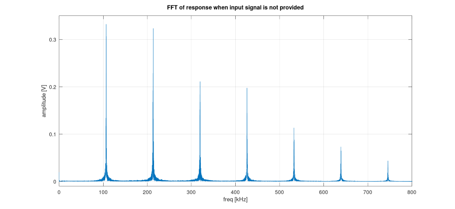
I run FFT analysis to check linearity of the amplifier. To do that I exported amplifier responses from oscilloscope software to csv, then using MATLAB script I generated their FFT plots. I considered two cases: when no input was provided to the amplifier and when amplifier got 1kHz sine wave with amplitude 200mA.
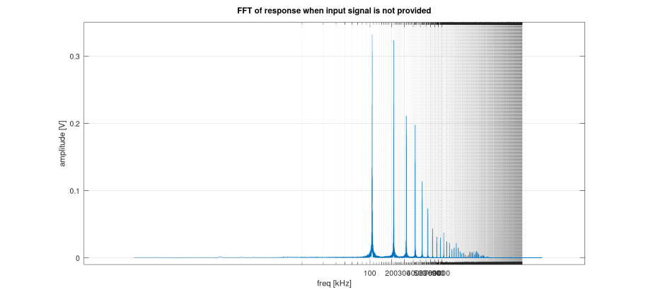
FFT plots of the response when no input is provided:
- Linear plot:
- Logarithmic plot:
Logarithmic FFT plot of the amplifier response to sine wave with frequency 1kHz and amplitude 200mV:
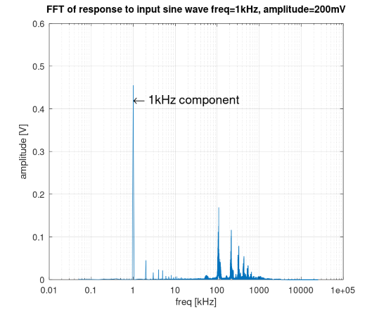
From these plots it is clear that the amplifier runs into self-oscillations. When no input is provided, the amplifier generates a signal at frequencies being approximately multiples of 100kHz. When the 1kHz signal is provided as an input signal of the amplifier, 1kHz frequency is also present as the highest stripe on the FFT plot. However, there are also visible small stripes at multiples of 1kHz, which indicates a high THD. Moreover, there is also the self-oscillation at frequencies being multiples of 100kHz (including 100kHz frequency). This is similar to the previous plot, but the amplitudes of the self-oscillation stripes are smaller, when input is provided to the amplifier.
Self-oscillations are unacceptable for the amplifier. These oscillations were not audible directly, because they were beyond frequency range of human hearing, but they might affect quality of sound and from aesthetical point of view it was really ugly. THD was also too high - I did not calculate it, because stripes coming from self-oscillation which are not a part of THD would need to be included.
3. Addressing defects of the amplifier
I identified two main problems with my amplifier: self-oscillation and large current consumption. This section describes how I tried to fix these issues and what were the results of those fixes.
3.1 Large current consumption
Current drawn by the output stage of the amplifier was around 1.5A. This was much bigger than current drawn by output stage load (it is not the same as output stage!) on simulations (415 mA root mean square). Large current was drawn in idle state (no amplifier input) as well as in active state (amplifier input present).
Unfortunately lots of the drawn current was wasted by dissipating into heat on power transistors and resistors instead of being delivered to loudspeaker. Within a few minutes of turning on radiators were becoming hot. The amplifier needed to be turned off then to cool radiators, because of the risk of damaging the electronic elements.
The cause of large current consumption was not clear at the beginning. However after resolving the second amplifier defect, which was self-oscillation, current consumption was greatly reduced, so probably large current was drawn by self-oscillation.
Since at the beginning I suspected that the circuit design required so much current I decided only to prevent overheating of elements. To cool radiators I installed a ventilator on each of them. This partially solved the problem. Radiator were getting hot much slower, however after a some longer time they were becoming hot again. Also cement resistors R4 and R18 were becoming hot after some time since turning on. At this point I decided to proceed to the next amplifier issue. Solving the second issue also solved current consumption problem, so I did not need to bother about overheating of elements anymore.
3.2. Self-oscillation of the circuit
FFT analysis of oscilloscope output showed that circuit was running into self oscillation at frequencies being multiples of 100kHz. This was a major problem, since it might affect quality of sound and it was not clear where was the source of the issue. I did not put decoupling capacitors on supply rail, which could be a source of a feedback loop which in turn could be a source of oscillation.
I put a few decoupling capacitors on supply rails and checked amplifier response again. The output in idle state was still a big (a few volts) garbage. When a sine wave was provided on the input, the output resembled sine wave a little, but there was much noise and distortion in it. The sound it produced was rather clear sine wave sound however. I looked at FFT of amplifier response again. The oscillation had flattened a lot, but it still remained.
Therefore I tried adding a new capacitor near main amplifier feedback loop. First I added a capacitor in parallel with R17 as a compensation capacitor, but it did not help. Then I added the capacitor with one end located between R17 and RV1 and the second end connected to the ground. I also calibrated potentiometers located in feedback loop: RV1 and RV4. This helped a lot. Oscillations disappeared. Output produced by amplifier in idle state was reduced to around 20 mV (compared to previous a few volts). After providing a sine wave to the amplifier, the output returned an amplified sine wave with minor noise garbage The sound of loudspeaker connected to amplifier became clearer. Also current consumption dropped a lot. Depending on sound volume, the amplifier drawn between around 150 mA in idle state up to 400 mA, when loud music was turned on (compared to previous 1.5A).
4. Casing
After successful startup of the amplifier I needed two separate casings for amplifier board and powering board.
4.1 Amplifier casing
The casing for amplifier board was printed on a 3D printer. It has the following external elements on its surface:
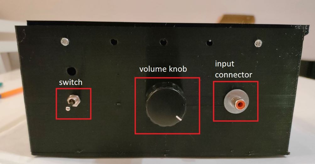
- switch for turning the amplifier on and off - transmits or blocks powering supply from powering connector to the board
- volume knob - regulates sound volume with an underlying potentiometer. It transmits signal from input connector to the board input.
- input connector - implemented as cinch socket, allows to plug in cable with input signal. The signal is passed to input potentiometer.
- two loudspeaker connectors (NK0027 LOGILINK) - transmit output signal from the board to the loudspeaker.
- powering connector - delivers power from the powering board. It has three channels (positive and negative rails and ground).
I placed the board in the casing using spacers and soldered all forementioned connections.
Additionally I drilled around 30 small ventilation holes to provide air exchange within the casing.
Amplifier board inside the casing:
Front side of the casing:
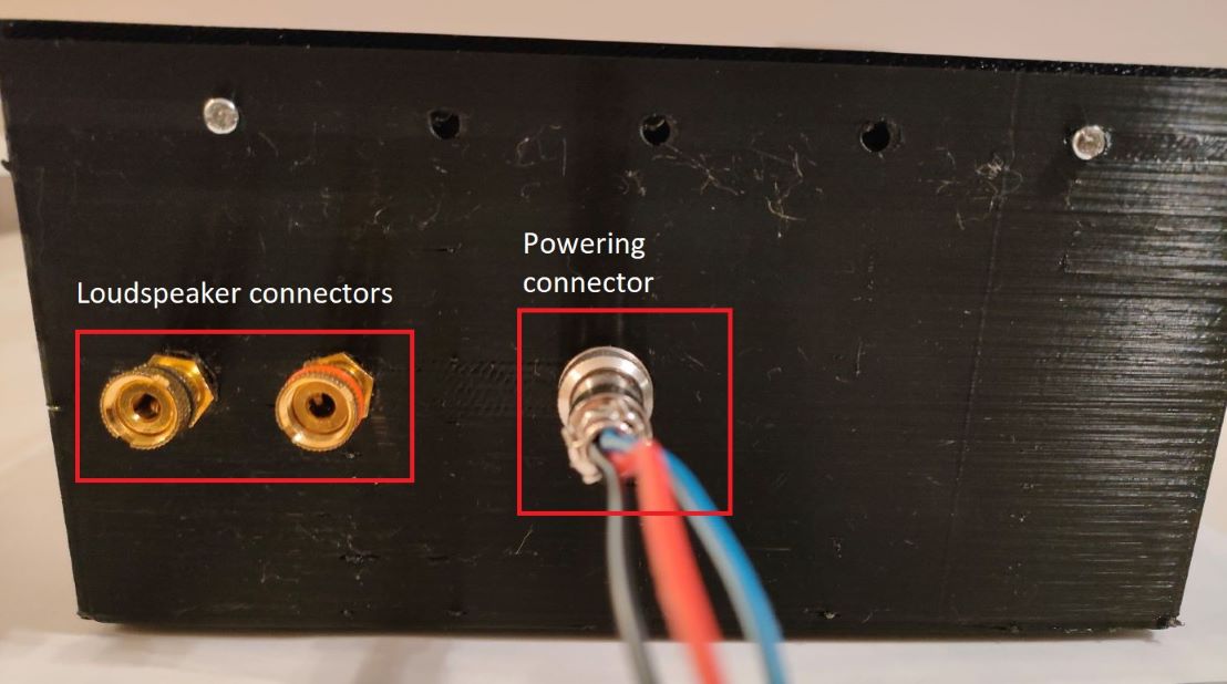
Back side of the casing:
Heat test
I wanted to check if the temperature inside the closed casing does not get too high within prolonged operation of the device. To do that I threaded a thermocouple through one of the ventilation holes, closed the covering of the casing, turned on the music (moderate volume) and measured temperature on the thermocouple throughout an hour. The result: Temperature increased by 3 Celsius degrees within 40 minutes and after that remained unchanged. The outcome was satisfying - I assumed that there is no risk of amplifier overheat.
4.2 Powering board
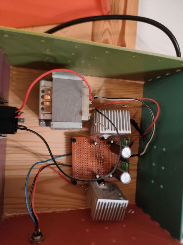
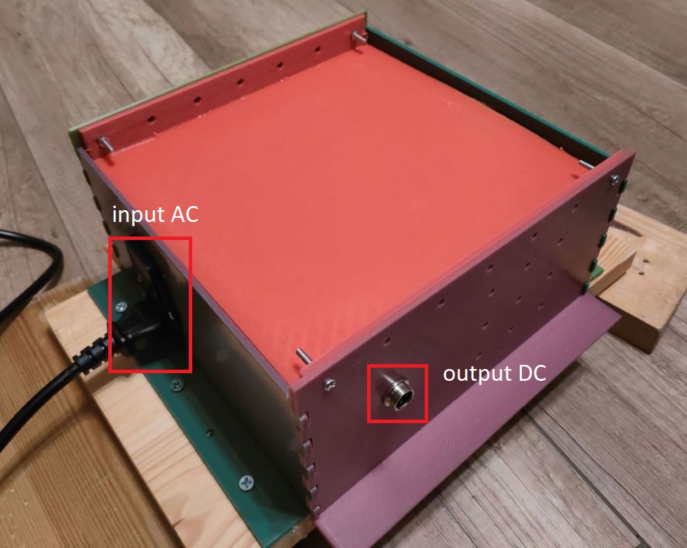
Casing for powering board needed to be less susceptible to deformations than amplifier casing, because transformer was also to be put into the casing and its weight was around 1kg. I would either need to print a very thick casing on a printer or use another solution. Finally I decided to make the bottom of the casing of the wood. Vertical walls and covering were printed on the 3D printer.
As a final result the casing had the following external elements on its surface:
- AC connector - delivers energy from power grid to the board’s transformer
- output DC connector - conveys DC produced by the board. It has three channels (positive and negative rails and ground). The connector delivers current for the main amplifier board
Additionally I drilled around 20 small ventilation holes to provide air exchange within the casing. I placed the board in the casing using spacers and soldered all forementioned connections. Transformer was attached to the wooden bottom by screws.
Photo of the casing:
4. Operation of the final amplifier device
After placing both boards in casings I ensured, that they can be operated through casing connectors. After that I connected output DC connector from power board to powering connector of amplifier board. I attached loudspeaker to amplifier’s output and PC’s sound connector to amplifiers input and played some music. The music sounded pretty clear. The only pitfall was loud operation of ventilators placed in amplifier casing.
As a final test I run frequency analysis of the amplifier.
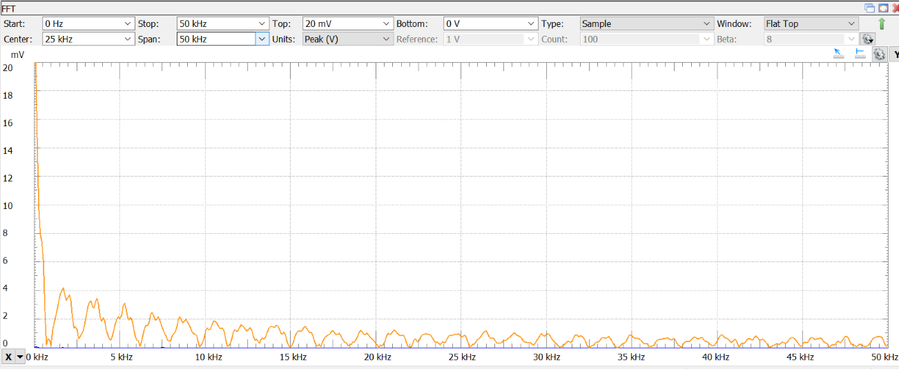
In the idle state amplifier produced spikes of a few mV (circa 4mV):
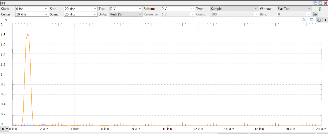
For the sine wave of 1kHz and unknown amplitude (I did not measure voltage signal amplitude coming from PC) the amplifier produced 1kHz spike of around 1.8V and a few smaller spikes at multiples of 1kHz. Spike at 2kHz was around 25mV, later multiples were much smaller:
I also measured the current drawn by the amplifier. With KORAD power supply the information about drawn current was provided on the device display. With DIY power supply it was more difficult. I took current consumption measurement device for power grid, plugged it to the point where powering board was supplied with AC and measured consumed current. Reported current was around 0.1A for loud music around 0.079A when no music was played. Between amplifier board and electric grid supply there was a transformer. So to obtain real current drawn by the board, measured current had to be scaled by a factor of \(\frac{U_{in}}{U_{out}}=\frac{230V}{12V}\). From this formula it could be derived that the current drawn by the board was 1.91A when loud music was playing and 1.3A when no music was playing. This is much bigger than what was previously measured with KORAD device. However, power supply board also requires some energy for operation so part of current was used there. Also, current consumption measurement device was probably not very accurate. Therefore I suppose that current usage for amplifier board was more close to 100-400mA range than to 1A.